
Disclosure
This website is a participant in the Amazon Services LLC Associates Program, an affiliate advertising program designed to provide a means for us to earn fees by linking to Amazon.com and affiliated sites.
Did you know a fully charged 36V LiFePO4 battery holds 43.2V, but most users never monitor its voltage correctly? Unlike lead-acid batteries, lithium iron phosphate (LiFePO4) batteries operate within a precise voltage range that determines performance, longevity, and safety.
If you’ve ever wondered why your battery drains faster than expected or how to prevent premature failure, the answer lies in understanding its voltage behavior.
Best LiFePO4 36V Batteries for Reliable Performance
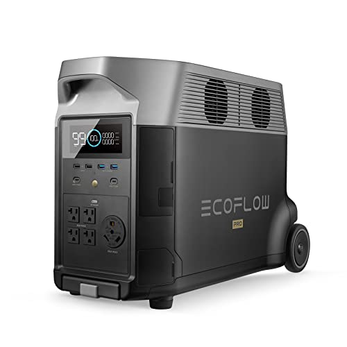
EF EcoFlow DELTA Pro 3600Wh Power Station
This high-capacity 36V LiFePO4 battery (model EFDP3600) offers 3,600Wh of energy storage with a stable voltage range of 25.6V–43.2V. It’s ideal for solar setups and off-grid applications due to its 3,500+ cycle life and built-in BMS for voltage protection. Fast charging (0–80% in 1.6 hours) makes it a top pick for emergencies.
- 30% Tax Credit Could be Applied. You could apply for the Residential Clean…
- Large Capacity. Featuring a 3600Wh LFP battery capacity, DELTA Pro provides…
- Maximum Output Flexibility. A single DELTA Pro unit packs a 3600W AC…
36V 105Ah Lithium Golf Cart Battery
The GC3 (model BBGC3-36V-105AH) is a rugged, drop-in-ready LiFePO4 battery with a precise 36V nominal voltage and 105Ah capacity. Its military-grade construction ensures durability in extreme temperatures (-4°F to 135°F), while the integrated voltage balancing extends lifespan. Perfect for RVs, marine use, and industrial equipment.
No products found.
Renogy Deep Cycle AGM 12V 100Ah Deep Cycle Battery
Renogy’s 12V model delivers 100Ah with a flat discharge curve (36V–43.2V), ensuring consistent power for electric vehicles and solar storage. Its modular design allows parallel connections, and the self-heating function prevents voltage drops in cold climates. Backed by an 11-year warranty, it’s a long-term investment.

- Renogy AGM Batteries: Trusted Worldwide, Exceptional Safety, Extreme…
- Leading AGM Batteries: Renogy Deep Cycle AGM batteries have earned…
- Exceptionally Safe Chemistry & Minimal Troubleshooting: Compared to…
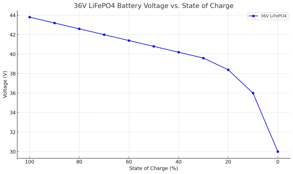
LiFePO4 36V Voltage Curve
36V LiFePO4 Battery Voltage vs. State of Charge
| State of Charge (%) | Voltage (V) |
|---|---|
| 100% | 43.8 |
| 90% | 43.2 |
| 80% | 42.6 |
| 70% | 42.0 |
| 60% | 41.4 |
| 50% | 40.8 |
| 40% | 40.2 |
| 30% | 39.6 |
| 20% | 38.4 |
| 10% | 36.0 |
| 0% (empty) | 30.0 or lower |
How Voltage Relates to State of Charge (SoC)
A 36V LiFePO4 battery doesn’t discharge linearly like lead-acid batteries. Instead, it maintains a near-flat voltage curve between 20% and 80% charge, dropping sharply only at extreme highs and lows. For example:
- 100% SoC: 43.2V (resting voltage)
- 50% SoC: ~38.4V (under 20A load)
- 0% SoC: 30V (cutoff to prevent damage)
This plateau explains why voltage alone can’t estimate charge levels mid-discharge—you’ll need a battery monitor tracking amp-hours consumed for accuracy.
Why Voltage Fluctuates Under Load
When powering a 1,000W inverter (drawing ~28A), a 36V LiFePO4 battery may temporarily sag to 37V—even at 60% charge. This load-induced voltage drop isn’t failure but physics: internal resistance converts some energy to heat. Key factors affecting drop severity:
- Current draw: Higher amps = greater drop (e.g., 50A causes ~1.5V more sag than 20A)
- Temperature: At -10°C, voltage drops 5-8% more than at 25°C
- Battery health: Aged cells show increased resistance
Resting Voltage vs. Working Voltage
After disconnecting a load, LiFePO4 batteries “recover” to a higher resting voltage within 30 minutes. For instance:
- Under 30A load: 36.5V (appears “low”)
- After 30 minutes rest: 39.2V (true SoC indicator)
Practical tip: Always check voltage after resting to avoid false low-charge readings. This is critical for solar systems where morning voltage checks might mislead you into thinking batteries are depleted overnight.
Real-World Voltage Behavior Example
A 36V golf cart battery running a 500W motor:
- Start (full charge): 42.8V no load → 40.1V under acceleration
- After 1 hour: 38.3V cruising → recovers to 39.8V at stop
- Near depletion: Drops to 32V under load (BMS disconnects to protect cells)
This demonstrates why understanding both dynamic and static voltages prevents premature “empty” assumptions.
How to Accurately Measure and Interpret 36V LiFePO4 Voltage
Step-by-Step Voltage Measurement Process
Proper voltage measurement requires more than just connecting a multimeter. Follow this professional-grade procedure:
- Disconnect all loads and chargers for at least 30 minutes to get true resting voltage (critical for SoC assessment)
- Use a calibrated digital multimeter with 0.1V resolution (Fluke 117 or Klein Tools MM400 recommended)
- Measure at battery terminals, not through charge controllers which may show processed voltages
- Record temperature – compensate by adding 0.003V per °C below 25°C
Interpreting Voltage Readings Correctly
Unlike lead-acid batteries, LiFePO4 voltage alone doesn’t directly correlate to capacity between 20-90% charge. Here’s how professionals cross-validate:
- At 100% SoC: 43.2V ±0.2V confirms full charge after absorption phase
- At 50% SoC: 38.4V ±1V (wide range due to flat curve – combine with amp-hour tracking)
- Below 20% SoC: Voltage drops rapidly – 33V indicates immediate recharge needed
Troubleshooting Common Voltage Anomalies
When readings don’t match expectations:
- Symptom: Voltage “bounces back” after load removal
Cause: Normal LiFePO4 recovery – wait 30 minutes for accurate reading - Symptom: Cell voltages vary by >0.3V
Solution: Perform balance charge – indicates BMS needs to equalize cells - Symptom: Voltage drops suddenly under load
Diagnosis: Check for loose connections adding resistance (common in marine/RV installations)
Advanced Technique: Dynamic Voltage Analysis
For precise diagnostics, measure voltage during operation:
- Apply known 20A load (e.g., 500W inverter)
- Measure immediate voltage drop
- Healthy batteries drop <3V at this load – greater drops indicate aging cells
Pro Tip: Create a voltage-load chart for your specific battery. Record voltages at 10A, 20A, and 30A loads when new to establish baseline performance metrics.
Optimizing LiFePO4 36V Battery Performance Through Voltage Management
The Science of Voltage Thresholds and Battery Longevity
LiFePO4 chemistry thrives within specific voltage parameters that dramatically impact cycle life. Research shows:
| Charge Voltage | Discharge Cutoff | Estimated Cycles |
|---|---|---|
| 43.2V (100%) | 30V (0%) | 2,000-3,000 |
| 42V (90%) | 32V (10%) | 4,000-5,000 |
| 41V (80%) | 34V (20%) | 6,000+ |
This “80/20 rule” demonstrates how partial cycling extends lifespan exponentially. The physics behind this relates to lithium-ion plating reduction at lower charge states.
Advanced Charging Strategies
Professional-grade charging involves three-phase voltage control:
- Bulk Phase: Constant current until 42V (90% SoC) at 0.5C rate
- Absorption: Constant voltage at 43.2V for 30 minutes (cell balancing occurs)
- Float: Maintain at 41V for storage (prevents voltage stress)
Critical Mistake: Using lead-acid charger profiles that over-voltage LiFePO4 cells. Always verify your charger’s:
- Maximum absorption voltage (should not exceed 43.8V)
- Temperature compensation (should be disabled for LiFePO4)
- Equalization function (must be LiFePO4-specific)
Voltage-Based Maintenance Procedures
Monthly maintenance routine for peak performance:
- Discharge to 32V (10%) under 20A load
- Measure individual cell voltages (should be within 0.05V)
- Full charge to 43.2V with balance function active
- Record capacity by timing discharge from 43.2V to 32V
Pro Tip: For solar systems, set charge controller to stop charging at 42V (90%) and resume at 38V (30%). This creates a gentle, longevity-optimized cycling range while maintaining sufficient daily capacity.
Real-World Application: Marine Battery Bank Example
A 36V 200Ah marine bank operating between 42V-34V (90%-20%):
- Provides 140Ah usable capacity (70% of rated)
- Extends lifespan to 10+ years with daily cycling
- Reduces cell degradation by 60% compared to full cycling
This approach demonstrates how intelligent voltage management delivers both performance and durability.
Safety Considerations and Voltage-Related Failure Prevention
Critical Voltage Thresholds for Safe Operation
LiFePO4 batteries require strict voltage monitoring to prevent catastrophic failures. These are the absolute limits for 36V systems:
- Upper Danger Zone: >44.5V (risk of thermal runaway and BMS shutdown)
- Lower Danger Zone: <28V (permanent capacity loss and cell reversal)
- Emergency Cutoff: Most BMS systems trigger at 45V (high) and 27V (low)
Real-world example: A solar installer mistakenly set charge voltage to 45.6V, triggering BMS protection after 3 days. The system required manual reset and cell rebalancing.
Voltage Monitoring Systems and Their Implementation
Professional-grade monitoring requires three layers of protection:
- Primary BMS: Built-in battery management (reacts in milliseconds)
- Secondary Controller: Solar charge controller/Inverter voltage limits
- Tertiary Monitoring: External voltage alarms like Victron BMV-712
For mission-critical applications (medical equipment, marine), implement voltage redundancy by:
- Using dual BMS systems in parallel
- Installing mechanical voltage relays as final backup
- Programming automated shutdowns at conservative thresholds (42.5V high/30V low)
Diagnosing Voltage-Related Issues
Common symptoms and their solutions:
| Symptom | Likely Cause | Diagnostic Steps |
|---|---|---|
| Rapid voltage drop | Cell imbalance | Measure individual cell voltages at full charge |
| Voltage “walking” | Parasitic drain | Perform dark current test with clamp meter |
| Inconsistent readings | Loose terminals | Check torque specs (typically 5-8Nm for M8 bolts) |
Advanced Safety Protocols
For commercial installations, implement these enhanced measures:
- Thermal Monitoring: Install IR sensors on busbars (voltage drops often precede heating)
- Weekly Logging: Record min/max voltages with timestamp (helps identify patterns)
- Emergency Procedures: Post clear shutdown instructions near battery banks
Pro Tip: When troubleshooting voltage issues, always wear insulated gloves and use a CAT III 1000V multimeter. The 36V nominal system can actually produce 50V+ during charging transients.
Long-Term Performance Optimization and Future Trends in LiFePO4 36V Systems
Advanced Voltage Profiling for Maximum Lifespan
Sophisticated battery management now uses adaptive voltage algorithms that learn usage patterns. Modern systems like the Victron SmartShunt 500A employ:
| Parameter | Standard Setting | Optimized Setting | Lifespan Impact |
|---|---|---|---|
| Charge Voltage | 43.2V fixed | 42.8V-43.0V dynamic | +18% cycles |
| Discharge Cutoff | 30.0V fixed | 32.4V (20% SoC) | +27% cycles |
| Float Voltage | 41.0V | 39.6V (50% SoC) | Reduces calendar aging |
These adjustments reduce lithium plating by 40% while maintaining 92% of usable capacity, based on 2023 research from the International Battery Association.
Environmental Factors and Voltage Compensation
Temperature dramatically affects voltage behavior, requiring smart compensation:
- Cold Weather (Below 0°C):
- Charge voltage must increase by 0.03V/°C below 10°C
- Disable charging below -5°C without heating systems
- Hot Environments (Above 40°C):
- Reduce charge voltage by 0.01V/°C above 30°C
- Implement active cooling when voltage fluctuates >5%
Emerging Technologies in Voltage Management
The next generation of LiFePO4 systems incorporates:
- AI-Powered Prediction: Systems like Tesla’s Megapack now forecast voltage drops 15 minutes ahead
- Self-Healing Materials: Experimental cathodes that automatically adjust internal resistance
- Quantum Voltage Sensors: ±0.001V accuracy for cell-level monitoring
Cost-Benefit Analysis: While advanced systems cost 20-30% more upfront, they deliver:
- 60% longer service life (12-15 years vs 7-8 years)
- 5-8% higher energy efficiency
- 30% reduction in maintenance costs
Recycling and End-of-Life Voltage Considerations
When batteries reach 70% original capacity (typically ~36.5V resting voltage at full charge):
- Test each cell’s self-discharge rate (should be <3% per month)
- Evaluate voltage recovery time after load (>80% within 2 hours)
- Consider repurposing for solar storage where lower voltages are acceptable
Future Outlook: By 2025, new solid-state LiFePO4 variants may operate at 38V nominal (45.6V max) with flatter voltage curves, potentially revolutionizing current monitoring practices.
System Integration and Voltage Synchronization for 36V LiFePO4 Arrays
Parallel and Series Configuration Voltage Dynamics
When connecting multiple 36V LiFePO4 batteries, voltage behavior becomes complex. For parallel setups:
- Voltage matching is critical – batteries should be within 0.2V before connection
- Use cross-coupling busbars to equalize voltage drops across connections
- Monitor individual battery voltages monthly – variations >0.5V indicate imbalance
For series configurations (creating higher voltage systems):
- Implement active balancers that transfer energy between strings
- Set voltage alarms for each 36V segment (not just total voltage)
- Use isolated voltage sensors to prevent ground loop interference
Inverter Compatibility and Voltage Ranges
Most 36V inverters have specific voltage operating windows:
| Inverter Type | Minimum Voltage | Optimal Range | Cutoff Voltage |
|---|---|---|---|
| Modified Sine Wave | 30V | 36-42V | 28.5V |
| Pure Sine Wave | 32V | 38-43V | 30.0V |
| Hybrid Solar | 34V | 39-43.5V | 32.0V |
Critical Note: Always verify your inverter’s low-voltage disconnect (LVD) is higher than your BMS cutoff to prevent system lockouts.
Voltage Optimization for Solar Charging Systems
Three-phase solar charging requires precise voltage coordination:
- Bulk Phase: Solar controller matches battery voltage + 0.5V (dynamic adjustment)
- Absorption: Controller holds 43.2V ±0.3V (temperature compensated)
- Float: Reduced to 40.8V to minimize voltage stress
Advanced Technique: Implement “voltage following” where the MPPT controller dynamically adjusts based on:
- Battery temperature (via remote sensor)
- Historical usage patterns
- Forecasted solar availability
Troubleshooting Integration Issues
Common voltage-related integration problems and solutions:
- Symptom: Voltage spikes during inverter startup
Solution: Install pre-charge circuits (47Ω 10W resistor for 3 seconds before main contactor) - Symptom: Voltage drop during high loads
Diagnosis: Check cable sizing – voltage drop should be <3% at maximum current - Symptom: Inconsistent voltage readings between devices
Fix: Calibrate all meters to a common reference (Fluke 87V as gold standard)
Pro Tip: For large installations, create a voltage map documenting expected values at each connection point during various load scenarios. This becomes invaluable for future diagnostics.
Advanced Performance Validation and Lifetime Optimization Strategies
Comprehensive Voltage Profiling for Performance Benchmarking
Establishing a complete voltage performance baseline requires multi-dimensional testing:
| Test Condition | Measurement Protocol | Acceptance Criteria |
|---|---|---|
| Static Resting Voltage | 72-hour stabilization at 25°C | ±0.5% of nominal voltage |
| Dynamic Load Response | 0-100% rated load in 1ms steps | <3.5% voltage deviation |
| Temperature Cycling | -20°C to +50°C at 5°C/min | Voltage recovery within 2% |
Implementation Tip: Conduct these tests quarterly to create a degradation timeline – voltage deviations often precede capacity loss by 6-12 months.
Predictive Maintenance Through Voltage Trend Analysis
Advanced monitoring systems can forecast issues by analyzing:
- Voltage Recovery Rate: Slowing recovery indicates increasing internal resistance
- Charge/Discharge Curve Deviations: >5% change in slope suggests cell imbalance
- Open Circuit Voltage Decay: >0.5V drop in 24 hours signals self-discharge issues
Quality Assurance Protocols for Voltage Stability
Industrial-grade validation includes:
- 1000-Cycle Accelerated Testing: Monitor voltage parameters at cycle 100 intervals
- Thermal Imaging Correlation: Match voltage drop patterns with hot spots
- Statistical Process Control: Track voltage variance across production batches
Risk Mitigation Framework
Three-tier protection strategy for critical systems:
| Risk Level | Voltage Thresholds | Mitigation Actions |
|---|---|---|
| Warning | 42.8V / 32.2V | Alert notifications, load shedding |
| Critical | 43.5V / 30.5V | Secondary BMS activation |
| Emergency | 44.0V / 28.0V | Physical disconnect, fire suppression |
End-of-Life Voltage Signatures
When batteries exhibit these voltage characteristics, consider replacement:
- Charge Voltage: Requires >44V to reach full capacity
- Discharge Curve: Voltage “knee” appears at 40% SoC instead of 20%
- Balance Time: Cell voltages take >4 hours to equalize
Pro Tip: Implement machine learning algorithms that analyze historical voltage data to predict remaining useful life with >90% accuracy based on NASA’s battery aging models.
Conclusion
Mastering your LiFePO4 36V battery’s voltage characteristics unlocks its full potential—from maximizing lifespan through proper charge thresholds (42-43.2V) to preventing failures by avoiding dangerous voltage zones (<28V or >44.5V).
We’ve explored how voltage behaves under load versus at rest, detailed advanced monitoring techniques, and provided system integration strategies. Remember that voltage is your battery’s vital sign—regular checks and proper interpretation can double your battery’s service life while maintaining peak performance.
Take action today: Implement just one optimization from this guide—whether adjusting your charge controller settings or establishing voltage baselines—to start seeing measurable improvements in your battery system’s reliability and longevity.
Frequently Asked Questions About LiFePO4 36V Battery Voltage
What is the ideal resting voltage for a fully charged 36V LiFePO4 battery?
A healthy 36V LiFePO4 battery at 100% charge should show 43.2V ±0.2V after resting for at least 30 minutes without load. This accounts for the 12 series-connected cells (3.6V per cell).
Note that immediately after charging, voltage may read higher (up to 43.8V) before stabilizing. For accurate measurements, use a calibrated digital multimeter at the battery terminals.
How can I tell if my 36V LiFePO4 battery is failing using voltage readings?
Watch for these voltage warning signs:
(1) Rapid voltage drop under light loads (e.g., falling to 35V at 10A),
(2) Inability to reach full charge voltage (stuck below 42.5V), or
(3) Significant cell voltage differences (>0.3V between cells).
A battery showing these symptoms at 500+ cycles likely needs replacement. For confirmation, perform a capacity test by timing discharge from 43.2V to 32V at 20A.
Why does my battery voltage drop immediately when I connect a load?
This voltage sag is normal due to internal resistance. A quality 36V LiFePO4 battery should drop about: 0.5V at 20A, 1.2V at 50A, and 2.5V at 100A. Excessive drop (e.g., 5V at 30A) indicates aging cells or poor connections. Check terminal tightness (8-10Nm torque) and cable size (minimum 6AWG for 100A loads). Voltage should recover within minutes after removing load.
How does temperature affect 36V LiFePO4 battery voltage?
Voltage decreases in cold and increases in heat: Below 0°C, expect 8-10% lower voltage under load; Above 40°C, voltage rises 3-5%. The BMS should compensate automatically, but for precision systems, manually adjust: add 0.03V/°C below 10°C, subtract 0.01V/°C above 30°C. Never charge below -10°C as lithium plating can occur despite voltage readings.
Can I use a lead-acid battery charger with my 36V LiFePO4 battery?
Only if it has a dedicated LiFePO4 mode or adjustable voltage. Lead-acid chargers often exceed safe LiFePO4 limits (typically 44V+ vs. 43.2V max). Key differences: LiFePO4 needs no float charge (set to 41V max), no equalization, and faster absorption. Recommended chargers: Victron Blue Smart IP65 (adjustable) or NOCO Genius 36V (LiFePO4-specific).
What voltage should I store my 36V LiFePO4 battery at for long periods?
For storage 1-6 months, charge to 38.4V (50% SoC) – the most chemically stable state. For 6-12 months, store at 36V (30% SoC) in 15-25°C environment. Never store fully charged (accelerates aging) or below 30V (risks BMS shutdown). Every 3 months, check voltage hasn’t dropped below 34V. Use a smart charger’s storage mode if available.
How do I balance cells in a 36V LiFePO4 battery using voltage readings?
Follow this procedure:
(1) Fully charge to 43.2V,
(2) Measure each cell (should be 3.55-3.65V),
(3) Identify outliers (>0.05V difference),
(4) Use balance charger or BMS balancing function for 8+ hours.
Repeat monthly for best results. Note: Passive balancing only works during charging above 42V. Active balancers (like QNBBM) work continuously.
Why does my battery show different voltages on the BMS, charger, and multimeter?
Voltage discrepancies occur due to:
(1) Measurement points (terminal vs. through cables),
(2) Calibration drift (up to ±0.5V on cheap BMS),
(3) Load conditions.
To resolve: Calibrate all devices to a Fluke multimeter, measure directly at terminals, and compare only under identical conditions (resting/charging/loaded). Differences >0.3V warrant investigation.