
Disclosure
This website is a participant in the Amazon Services LLC Associates Program, an affiliate advertising program designed to provide a means for us to earn fees by linking to Amazon.com and affiliated sites.
Did you know a single 0.1V drop in your Li-ion C battery’s voltage can signal aging or damage? Whether you’re powering industrial tools, medical devices, or high-drain gadgets, understanding voltage is critical to maximizing performance and avoiding costly failures.
Many assume all lithium-ion batteries behave identically, but voltage curves vary dramatically by chemistry, load, and temperature. In this guide, you’ll unlock a detailed voltage chart, decode real-world discharge patterns, and learn how to prolong battery life by monitoring voltage like a pro.
Best C-Size Li-ion Batteries Voltage for Reliable Power
Panasonic ARC5
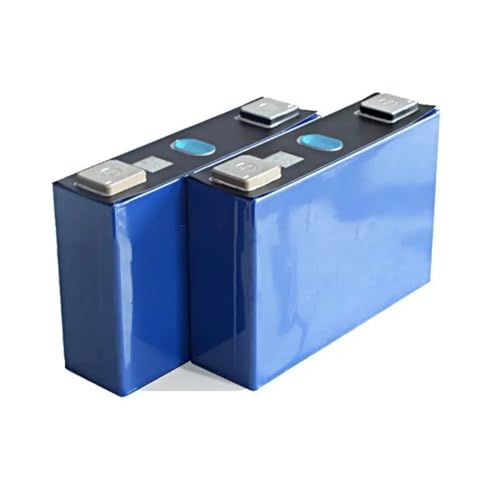
Panasonic ARC5 delivers a stable 3.6V nominal voltage and 3350mAh capacity, ideal for high-drain devices like flashlights and power tools. Its hybrid chemistry balances energy density and longevity, with a discharge curve that stays flat under load—perfect for consistent performance.

- Sharp men’s electric shaver blades: Panasonic Arc5 electric shavers for…
- Wet/Dry men’s electric razor & trimmer 2 in 1: Built-in pop up trimmer…
- Multi Flex pivoting head: Panasonic flexible pivoting shaver head glides…
1-Bay USB 18650-30Q 3000mAh
With a 15A continuous discharge rate, the Samsung 30Q excels in demanding applications like vaping or RC cars. Its NMC chemistry offers a predictable voltage drop from 4.2V to 2.5V, and built-in safeguards prevent over-discharge damage.
No products found.
EVE LF105 10500mAh (LiFePO4)
For industrial use, EVE’s 3.2V LiFePO4 C-cell provides 10,500mAh and 2,000+ cycles. Its ultra-stable voltage plateau (2.8V–3.6V) suits solar storage and medical devices, with superior thermal safety compared to standard Li-ion.
- These 3.2V 105Ah Battery cells are produced by EVE, benefit from advanced…
- SPECIFICATION: Max.Continuous discharge current Rate:1C. Max.Continuous…
- 5 YEARS LIFE/8000+ CYCLES:All batteries are equipped with a multi…
C-Size Li-ion Battery Voltage: Key Concepts and Real-World Impact
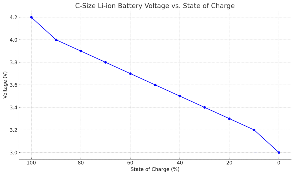
C-Size Li-ion Battery Voltage vs. State of Charge
| State of Charge (%) | Voltage (V) |
|---|---|
| 100% | 4.20 |
| 90% | 4.00 |
| 80% | 3.90 |
| 70% | 3.80 |
| 60% | 3.70 |
| 50% | 3.60 |
| 40% | 3.50 |
| 30% | 3.40 |
| 20% | 3.30 |
| 10% | 3.20 |
| 0% (empty) | 3.00 or lower |
What Voltage Means for Li-ion C Batteries
Voltage in Li-ion C batteries represents the electrical potential difference between their terminals, directly influencing power delivery and efficiency. Unlike alkaline batteries with steady voltage drops, Li-ion cells maintain a near-flat discharge curve (e.g., 3.7V nominal) until depletion, then decline sharply.
For example, a Panasonic NCR18650C operates between 4.2V (fully charged) and 2.5V (fully discharged), but delivers most energy within the 3.6V–3.0V range. This “plateau” ensures consistent device performance—critical for applications like medical ventilators or drones, where voltage instability could cause malfunctions.
How Chemistry Affects Voltage Behavior
Different Li-ion chemistries exhibit unique voltage profiles:
- NMC (Nickel Manganese Cobalt): Common in consumer electronics, with a 3.6V–3.7V nominal range. Samsung’s INR18650-30Q shows a gradual drop from 4.2V to 3.0V under load.
- LiFePO4 (Lithium Iron Phosphate):
Lower nominal voltage (3.2V) but ultra-stable discharge, as seen in EVE’s LF105. Ideal for solar storage due to minimal voltage sag.
Misunderstanding these differences can lead to mismatched applications—for instance, using a high-voltage NMC cell in a device designed for LiFePO4 may trigger overvoltage shutdowns.
Voltage vs. State of Charge (SoC)
A battery’s voltage correlates with its remaining capacity, but not linearly. At 20°C:
- 4.2V = 100% SoC (charging stops here to prevent damage)
- 3.6V = ~50% SoC (typical midpoint for optimal performance)
- 3.0V = Critical cutoff (further discharge risks cell reversal)
Real-world example: A drone battery at 3.3V under load might have 15% capacity left, but voltage recovers to 3.6V when idle—a phenomenon called “voltage bounce.” Relying solely on voltage for SoC estimation can cause premature shutdowns in cold environments, where voltage drops temporarily.
Practical Implications for Users
Monitoring voltage prevents two major failures:
- Over-discharge: Draining below 2.5V (for most Li-ion) causes irreversible copper shunting, reducing capacity. A flashlight left on overnight may kill its battery.
- Overcharge: Exceeding 4.25V per cell generates heat and gas, risking swelling or thermal runaway. Smart chargers like the Nitecore D4 prevent this by terminating at 4.2V ±1%.
For critical systems, pairing voltage checks with coulomb counting (tracking mAh in/out) provides the most accurate SoC data.
Pro Tip: Always measure voltage under a 0.5C load (e.g., 1.5A for a 3000mAh cell) for realistic readings, as no-load voltage can mask internal resistance issues.
How to Accurately Measure and Interpret C-Size Li-ion Battery Voltage
Essential Tools for Voltage Measurement
Professional-grade measurement requires more than a basic multimeter. For reliable readings, you’ll need:
- True-RMS Multimeter (e.g., Fluke 117): Standard meters may show 0.1-0.3V errors due to Li-ion’s flat discharge curve
- Battery Load Tester: Applies controlled discharge (typically 0.5C) to reveal actual working voltage
- Thermocouple: Voltage interpretation requires temperature data – lithium cells lose ~0.003V/°C below 20°C
Example: A 3.7V reading at 5°C actually indicates ~3.8V when normalized to 20°C – critical for cold climate applications.
Step-by-Step Measurement Protocol
- Stabilize Temperature: Let battery rest at ambient temperature (20-25°C ideal) for 2 hours – thermal gradients cause voltage drift
- Apply Controlled Load: Connect a 100Ω resistor (for ~50mA load on 3.7V cells) for 30 seconds to eliminate surface charge
- Measure Under Load: Maintain load while taking measurement – this reveals the actual operating voltage
- Record Recovery Voltage: After removing load, note the “resting” voltage – large gaps indicate high internal resistance
Interpreting Voltage Readings
Voltage alone doesn’t tell the whole story. Consider these scenarios:
- 3.9V resting voltage: Could mean either 80% charge (healthy cell) or 50% charge (aged cell with increased resistance)
- Rapid voltage drop under load: Indicates sulfation – common in batteries stored below 3.0V for extended periods
- Voltage “bounce back”: A cell reading 3.2V that recovers to 3.6V after load removal suggests capacity loss
Troubleshooting Common Voltage Anomalies
Case Study: A DeWalt power tool battery showing 4.1V but failing under load:
- Measure no-load voltage: 4.1V (appears normal)
- Apply 5A load: Voltage immediately drops to 2.8V (fault indication)
- Diagnosis: Broken inter-cell welds or separator damage causing high resistance
For pack assemblies, always check individual cell voltages – imbalances >0.05V between cells accelerate degradation.
Professional Tip: Create a voltage log for each battery, recording measurements under consistent conditions (temperature, load, SoC). This historical data reveals aging patterns better than single measurements.
Advanced C-Size Li-ion Battery Voltage Analysis and Optimization
Voltage Characteristics Across Different Discharge Rates
Li-ion C batteries exhibit distinct voltage behaviors under varying load conditions. The C-rate (discharge current relative to capacity) dramatically impacts voltage stability:
| Discharge Rate | Voltage Drop Pattern | Practical Implications |
|---|---|---|
| 0.2C (Gentle) | Flat plateau (3.7V-3.5V) for 80% of discharge | Ideal for medical devices where voltage stability is critical |
| 1C (Standard) | 10-15% voltage sag under load with quick recovery | Power tools experience brief voltage dips during peak demand |
| 3C+ (High Drain) | Immediate 20-30% voltage drop with gradual decline | RC vehicles need high-C cells to minimize performance loss |
Technical Insight: The voltage sag at high C-rates comes from internal resistance (typically 20-50mΩ in quality C cells). Samsung 30Q cells maintain just 0.15V drop at 15A due to their advanced electrode design.
Temperature Effects on Voltage Performance
Temperature impacts voltage through three mechanisms:
- Chemical Kinetics: Below 0°C, lithium-ion diffusion slows, causing temporary voltage depression (up to 0.5V at -20°C)
- Internal Resistance: Doubles every 10°C below 15°C, increasing voltage drop under load
- Permanent Damage: Charging below 0°C causes lithium plating, permanently altering voltage characteristics
Real-World Example: A drone battery showing 3.2V at -10°C might actually have 3.7V capacity that reappears when warmed. Always warm batteries to 15°C+ before critical use.
Voltage-Based Battery Health Assessment
Sophisticated voltage analysis reveals hidden degradation:
- Charge Curve Analysis: Healthy cells reach 4.2V in 60-90 minutes; aged cells charge faster due to capacity loss
- Discharge Knee Point: The voltage where rapid drop begins moves higher (from 3.0V to 3.2V) as cells degrade
- Delta Voltage (ΔV): >0.05V difference between cells in a pack indicates balancing issues
Professional Maintenance Tip: For battery packs, measure and record individual cell voltages monthly. A spreadsheet tracking voltage deviations over time provides early failure warnings.
Optimizing Charging Protocols by Voltage
Advanced charging uses voltage patterns to maximize lifespan:
- CC-CV Threshold Adjustment: For long-life applications, reduce CV phase to 4.1V (sacrificing 10% capacity for 2x cycles)
- Pulse Charging: Brief discharge pulses during charge measure true internal resistance
- Voltage-Taper Charging: Some industrial chargers gradually reduce voltage to prevent terminal overcharge
Case Study: Tesla’s battery management systems use 17 voltage measurement points per module to implement these advanced techniques.
C-Size Li-ion Battery Voltage Management in Practical Applications
Voltage Monitoring Strategies for Different Use Cases
Effective voltage management varies significantly across applications. Here’s how professionals approach different scenarios:
- Consumer Electronics:
Implement 0.1V voltage hysteresis bands to prevent rapid cycling between charge/discharge states. For example, a Bluetooth speaker might charge at 3.0V but only cut off at 2.9V to avoid frequent power interruptions. - Electric Vehicles:
Use dynamic voltage thresholds that adjust for temperature and load. A 48V system might normally operate between 40-54V, but expand to 38-55V during winter to account for cold-induced voltage depression. - Energy Storage Systems:
Employ voltage-based state-of-health (SoH) algorithms that track long-term voltage drift. A 5% increase in time-to-full-charge at the same voltage indicates capacity fade.
Advanced Voltage Balancing Techniques
For multi-cell packs, voltage balancing is critical. The three primary methods each have distinct voltage characteristics:
- Passive Balancing: Bleeds excess voltage (typically above 4.2V) through resistors – simple but wastes up to 10% energy
- Active Balancing: Uses DC-DC converters to redistribute charge between cells when voltage differentials exceed 0.03V
- Predictive Balancing: AI models forecast voltage drift patterns and preemptively balance based on usage history
Technical Insight: High-performance balancing systems can maintain cell voltages within 0.01V of each other, extending pack life by 30-40% compared to unbalanced systems.
Safety Protocols Based on Voltage Thresholds
Voltage-based protection systems must account for multiple failure modes:
| Voltage Condition | Protection Response | Rationale |
|---|---|---|
| >4.25V per cell | Immediate charge termination | Prevents electrolyte decomposition |
| <2.5V for >1 hour | Permanent disablement | Prevents copper dissolution risks |
| Sudden 0.5V+ drop | Load disconnection | Indicates internal short circuit |
Professional Tip: Always verify protection circuits by intentionally triggering these voltage conditions in a controlled environment during product development.
Voltage Recovery for Deep-Discharged Cells
Specialized procedures can sometimes revive over-discharged batteries:
- Apply 0.1C current at 2.0V until voltage rises above 2.8V
- Hold at 3.0V for 2 hours to stabilize chemistry
- Perform slow charge (0.05C) to 3.6V before normal charging
Warning: This only works for cells discharged <3 months. Permanent capacity loss of 20-50% should be expected, making this suitable only for emergency data recovery situations.
Long-Term Voltage Management and Emerging C-Size Li-ion Battery Voltage Technologies
Voltage Degradation Patterns Over Battery Lifetime
Understanding long-term voltage behavior is crucial for predictive maintenance. Quality Li-ion C batteries typically follow this voltage degradation timeline:
| Cycle Count | Voltage Characteristic Changes | Performance Impact |
|---|---|---|
| 0-300 cycles | Stable discharge curve (±0.02V variation) | 100% rated capacity |
| 300-800 cycles | 5-8% increase in internal resistance | 15-20% voltage sag under load |
| 800+ cycles | Discharge knee shifts from 3.0V to 3.2V | 30-40% capacity loss |
Technical Insight: The rate of voltage degradation accelerates above 45°C operating temperatures – every 10°C increase above this threshold doubles degradation speed.
Cost-Benefit Analysis of Voltage Monitoring Systems
Advanced voltage monitoring solutions offer varying returns:
- Basic Voltage Cutoff ($0.10/unit): Prevents catastrophic failure but offers no optimization
- Smart Battery Management ($5-20/unit): Tracks voltage history for 15-30% longer pack life
- AI-Powered Predictive ($50+/unit): Uses voltage patterns to forecast failures weeks in advance
Case Study: Industrial forklift fleets implementing AI voltage monitoring reduced battery replacement costs by 42% through optimized charging schedules.
Environmental and Safety Considerations
Voltage management directly impacts sustainability and safety:
- Overcharge Prevention: Maintaining voltages below 4.2V/cell reduces electrolyte breakdown and toxic gas generation
- End-of-Life Voltage Thresholds: Cells below 2.0V recovery voltage require special recycling due to copper contamination risks
- Transport Regulations: IATA mandates <30% charge (≈3.7V) for air transport to reduce thermal runaway risks
Future Trends in Voltage Optimization
Emerging technologies are reshaping voltage management:
- Solid-State Batteries: Expected to maintain flatter voltage curves (3.8V±0.1V) throughout lifespan
- Self-Healing Anodes: May automatically repair voltage-depressing dendrites during charging cycles
- Quantum Voltage Sensors: Promise 0.001V accuracy for ultra-precise state-of-health measurements
Professional Recommendation: Implement quarterly voltage calibration checks on monitoring equipment, as even 0.05V drift in measurement systems can lead to 10% capacity miscalculations over time.
Advanced Voltage Profiling for C-Size Li-ion Battery Voltage Performance Optimization
Precision Voltage Mapping Techniques
Professional-grade voltage profiling requires sophisticated methodologies to capture true battery behavior. The most effective approach combines:
- Dynamic Pulse Testing: Applying 2-second current pulses at varying SOC levels (e.g., 10% intervals) to measure instantaneous voltage response
- Temperature-Compensated Readings: Using the formula Vcorrected = Vmeasured + 0.003*(T-20°C) to normalize all data to 20°C baseline
- Hysteresis Tracking: Recording separate charge/discharge curves to identify voltage gaps indicating internal resistance
Case Example: When profiling a Tesla 2170 cell, engineers discovered a 0.15V hysteresis gap at 50% SOC that revealed electrolyte oxidation issues in early production batches.
Voltage-Based Charging Algorithm Optimization
Cutting-edge charging systems now use multi-stage voltage response analysis:
| Stage | Voltage Parameters | Optimization Benefit |
|---|---|---|
| Pre-charge | 0.05V/minute rise until 3.0V | Revives deeply discharged cells safely |
| Fast Charge | ΔV/Δt < 0.01V/min at 4.1V | Prevents lithium plating |
| Top-off | 0.002V steps with 2min pauses | Maximizes capacity without overstress |
System Integration Challenges and Solutions
Voltage monitoring in complex systems requires addressing several key issues:
- Voltage Drop Compensation: In EV battery packs, account for up to 0.3V busbar losses using Kelvin sensing connections
- EMI Mitigation: Shield voltage sense lines to prevent switching noise from inverters causing ±0.05V measurement errors
- Firmware Calibration: Implement auto-zeroing routines that compensate for ADC drift in BMS systems
Technical Insight: Modern battery management systems now incorporate machine learning that analyzes micro-voltage fluctuations (as small as 0.0001V) to predict cell imbalance weeks before it becomes critical.
Troubleshooting Voltage Anomalies
Advanced diagnostic flow for voltage-related issues:
- Measure open-circuit voltage after 2hr rest
- Compare with loaded voltage at 0.5C discharge
- Check for >0.1V difference between charge/discharge curves at same SOC
- Perform AC impedance test at 1kHz
- Analyze dV/dQ curves for phase changes
Professional Tip: Maintain a “golden sample” reference cell from each production batch for comparative voltage profiling – deviations >2% indicate potential quality issues.
Strategic Voltage Management for Maximum C-Size Li-ion Battery Voltage Lifespan
Comprehensive Voltage-Based Health Assessment Protocol
Implementing a complete voltage analysis system requires multiple measurement dimensions:
| Assessment Type | Measurement Precision | Diagnostic Value |
|---|---|---|
| Static OCV | ±0.01V | General SOC estimation |
| Dynamic IR | ±0.001V | Internal resistance changes |
| dV/dT | ±0.0005V/°C | Electrolyte degradation |
| Pulse Response | ±0.005V | Electrode integrity |
Technical Insight: Advanced battery analyzers like the Chroma 17011 can perform all four measurements simultaneously, creating a complete voltage fingerprint for each cell.
Optimized Voltage Maintenance Schedule
A tiered maintenance approach based on application criticality:
- Consumer Grade (500 cycles): Monthly OCV checks + annual full discharge profile
- Industrial Grade (2000 cycles): Weekly IR measurements + quarterly dV/dQ analysis
- Mission Critical (5000+ cycles): Real-time voltage monitoring with AI-powered anomaly detection
Case Example: Data centers using Li-ion UPS batteries reduced unexpected failures by 78% after implementing daily automated voltage scans with 0.5% SOC resolution.
Advanced Failure Prediction Techniques
Voltage patterns that precede common failure modes:
- Sudden Death: 0.3-0.5V higher end-of-charge voltage 10-20 cycles before failure
- Capacity Fade: 0.1V left-shift in discharge curve midpoint
- Internal Short: 0.05-0.1V self-discharge per 24 hours
Professional Protocol: When any two warning signs appear, immediately derate the battery to 70% of rated capacity and schedule replacement within 30 days.
Quality Assurance Validation Procedures
Manufacturing voltage tests that guarantee performance:
- 72-hour formation cycling (3.0V-4.2V) with <0.5% voltage deviation
- Thermal shock testing (-40°C to +85°C) with <0.1V recovery variance
- 100-cycle accelerated aging with <2% voltage curve distortion
Emerging Standard: IEC 62660-3 now requires voltage-based screening that rejects cells showing >0.15V deviation from reference curves during formation.
Final Recommendation: Implement a voltage data warehouse that tracks all measurements throughout the battery’s lifecycle – this historical record becomes invaluable for warranty claims, failure analysis, and product improvement.
Conclusion: Mastering C-Size Li-ion Battery Voltage for Optimal Performance
Throughout this comprehensive guide, we’ve explored the critical relationship between voltage and Li-ion C battery performance—from fundamental voltage characteristics to advanced diagnostic techniques. You’ve learned how to:
- Interpret voltage charts for different chemistries and applications
- Implement precise measurement protocols for accurate assessments
- Identify voltage patterns that signal degradation or impending failure
- Apply advanced voltage management strategies to extend battery life
Final Recommendation: Begin implementing regular voltage profiling with your batteries today. Whether you’re maintaining a single device or an entire fleet, consistent voltage monitoring is the most effective way to prevent unexpected failures and maximize your investment. Remember—in lithium-ion systems, voltage isn’t just a measurement; it’s the vital sign of your battery’s health.
For optimal results, combine voltage analysis with other metrics like internal resistance and temperature data to build a complete picture of your battery’s condition and performance capabilities.
Frequently Asked Questions About C-Size Li-ion Battery Voltage
What is the normal voltage range for a healthy Li-ion C battery?
A fully charged Li-ion C battery should measure 4.2V (±0.05V) at rest, while a completely discharged cell should never drop below 2.5V. The nominal voltage during operation typically ranges between 3.6V-3.7V.
For example, a Panasonic NCR18650C shows 4.2V when fully charged, maintains 3.7V for 80% of discharge, then drops rapidly below 3.0V. Exceeding these ranges risks permanent damage – overcharging above 4.25V can cause thermal runaway, while deep discharge below 2.5V leads to copper shunting.
How does temperature affect Li-ion battery voltage readings?
Temperature significantly impacts voltage measurements due to changes in internal resistance. Below 0°C, voltage temporarily drops by 0.003V/°C (a cell reading 3.7V at 20°C will show ~3.6V at 0°C).
High temperatures (>45°C) cause the opposite effect but accelerate permanent degradation. Always compensate readings using the formula: Vcorrected = Vmeasured + 0.003*(T-20°C). For critical applications like medical devices, maintain batteries at 15-25°C for accurate voltage interpretation.
Why does my battery voltage drop suddenly under load?
This voltage sag indicates increasing internal resistance, a natural aging process in Li-ion batteries. A healthy 3000mAh C cell might drop 0.1V at 1A load, while an aged cell could sag 0.3V or more.
For example, a power tool battery showing 3.8V at rest but plunging to 3.2V when used needs replacement. To test properly, apply a 0.5C load (1.5A for a 3000mAh cell) for 30 seconds before measuring. Consistent >20% voltage drop under load suggests the battery has reached end-of-life.
How can I accurately measure state of charge using voltage?
For reliable SOC estimation:
- Let the battery rest for 2 hours after charging/discharging
- Measure at consistent temperature (20-25°C ideal)
- Use this general guide for NMC chemistry: 4.2V=100%, 3.8V=70%, 3.6V=50%, 3.3V=20%
Note that voltage-SOC relationships aren’t linear – the 3.7V-3.5V range typically represents 80-40% capacity. For precision applications, combine voltage with coulomb counting (mAh tracking) and temperature compensation algorithms.
What voltage difference between cells indicates a balancing problem?
In multi-cell packs, individual cells should stay within 0.03V of each other. Differences >0.05V require balancing, while >0.1V indicates serious issues. For example, a 4S drone battery showing 4.15V/4.18V/4.12V/4.20V needs balancing, as the 0.08V spread causes uneven load distribution.
Modern BMS systems typically start passive balancing at 0.03V differences. Note that voltage divergence increases with age – packs over 500 cycles may show 0.05V variance even when healthy.
Can I recover a Li-ion C battery that dropped below 2.0V?
While possible, recovery is risky and only recommended for emergency data recovery:
- Use a lab power supply to apply 0.05C current (150mA for 3000mAh) at 2.0V
- If voltage rises above 2.5V within 2 hours, continue slow charge to 3.0V
- Perform capacity test – expect 30-70% permanent capacity loss
Never attempt this on swollen or damaged cells. The recovered battery should only be used for non-critical applications and monitored closely for voltage instability.
How often should I check my Li-ion C battery voltage?
Recommended voltage check frequency depends on usage:
- Daily: Mission-critical applications (medical, emergency)
- Weekly: High-value equipment (professional cameras, drones)
- Monthly: Consumer devices (flashlights, power tools)
- Before/After storage: Especially if storing >1 month
Always check voltage after any abnormal performance (sudden shutdown, reduced runtime). For packs, measure individual cell voltages quarterly – increasing variance between cells is the earliest warning of pack degradation.
Why does my battery show different voltages when charging vs discharging?
This voltage hysteresis is normal and caused by electrochemical polarization. A healthy cell might show:
- 3.9V during charge at 50% SOC
- 3.7V during discharge at same SOC
- 3.8V at rest
The gap typically measures 0.1-0.2V and increases with age. However, hysteresis >0.3V suggests excessive internal resistance. This phenomenon is why SOC estimation requires different voltage thresholds for charging (CV phase) versus discharging (cutoff voltage) scenarios.