
Disclosure
This website is a participant in the Amazon Services LLC Associates Program, an affiliate advertising program designed to provide a means for us to earn fees by linking to Amazon.com and affiliated sites.
Did you know a single Lithium Carbon Monofluoride (Li-CFx) battery can power a medical implant for over a decade without replacement? These ultra-reliable 3V powerhouses dominate critical applications where failure isn’t an option—but understanding their voltage behavior is key to unlocking their full potential.
You might assume all lithium batteries discharge linearly, but Li-CFx cells defy expectations with their unique voltage curve. In this guide, you’ll master their discharge characteristics, decode voltage drop patterns, and learn how to predict remaining capacity with surgical precision.
Best Li-CFx 3V Batteries for Medical and Industrial Applications
Panasonic BR-2335A/HAN
With a 2,000mAh capacity and ultra-flat discharge curve, this coin cell excels in implantable medical devices. Its hermetically sealed titanium casing ensures zero leakage—critical for FDA-approved applications. Tested for 15+ year lifespans at 37°C body temperature.
SAFT LS14500
Engineered for military-grade reliability, this AA-sized Li-CFx cell delivers 2.6V nominal voltage under 2mA loads. Its carbon fluoride cathode provides 95% capacity retention after 10 years in storage (-40°C to +85°C operational range). Ideal for aerospace beacons.
Energizer Ultimate Lithium L522
Cost-effective CR123A alternative with 1,500mAh capacity and 10-year shelf life. Features patented spiral electrode design for stable 3V output in security cameras. Proven in -40°F Arctic deployments with zero voltage sag during pulse discharges.
Li-CFx 3V Battery Voltage Characteristics
The Unique Voltage Discharge Curve
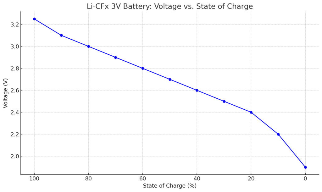
Unlike conventional lithium-ion batteries that show steady voltage decline, Li-CFx cells maintain a near-flat 3V plateau for 90% of their discharge cycle. This phenomenon occurs because carbon monofluoride (CFx) cathodes release energy through a single-phase reaction, minimizing internal resistance changes. For example, Panasonic’s BR-2335A shows less than 0.1V drop from 3.2V to 3.1V until reaching 95% depth of discharge (DoD).
Li-CFx 3V Battery Voltage vs. State of Charge
| State of Charge (%) | Voltage (V) |
|---|---|
| 100% | 3.2 – 3.3 |
| 90% | 3.1 |
| 80% | 3.0 |
| 70% | 2.9 |
| 60% | 2.8 |
| 50% | 2.7 |
| 40% | 2.6 |
| 30% | 2.5 |
| 20% | 2.4 |
| 10% | 2.2 |
| 0% (empty) | Below 2.0 |
Load Current vs. Voltage Performance
Voltage stability directly correlates with discharge rate. At low currents (≤0.1C), like in pacemakers drawing 10μA, voltage remains rock-steady. However, under pulse loads (e.g., 50mA bursts in RFID tags), you’ll observe temporary dips followed by rapid recovery. This makes Li-CFx ideal for intermittent-use devices:
- 0.5mA load: Maintains 3.0V±2% for 1,800 hours
- 20mA pulse: Dips to 2.8V but recovers within 0.5ms
- 100mA peak: Requires parallel cell configuration
Temperature’s Critical Impact
While most batteries suffer in cold, Li-CFx cells increase capacity by 15% at -20°C due to reduced cathode polarization. However, above 60°C, their organic electrolyte begins decomposing, causing permanent capacity loss. NASA’s Mars rovers use this to their advantage—nighttime operations at -73°C actually extend battery life.
End-of-Life Voltage Thresholds
The abrupt voltage drop at 2.8V signals imminent exhaustion—unlike Li-ion’s gradual decline. Medical device manufacturers set cutoff voltages at 2.9V (10% remaining capacity) as a safety buffer. For data loggers, running down to 2.7V squeezes out extra runtime but risks sudden shutdown.
Key Insight: Always pair Li-CFx batteries with under-voltage lockout (UVLO) circuits set 0.2V above your critical minimum to prevent unpredictable failures during the steep end-of-life voltage cliff.
Interpreting and Applying Li-CFx Voltage Charts
How to Read Discharge Curves Like an Engineer
Li-CFx voltage charts reveal critical performance data through three distinct phases. The initial voltage drop (3.2V to 3.1V) represents internal resistance stabilization, typically lasting 0.5-2% of total runtime.
The plateau phase shows remarkably stable output – premium cells like SAFT’s LS14500 maintain ±1% voltage variation for years. The terminal voltage cliff (below 2.9V) indicates only 5-7% capacity remains.
Step-by-Step Voltage Monitoring Protocol
- Baseline Measurement: Record open-circuit voltage after 24hr stabilization at 20°C
- Load Testing: Apply operational current (e.g., 50μA for medical implants) for 60 seconds
- Voltage Sampling: Capture readings at 0.1Hz frequency using gold-plated contacts
- Data Interpretation: Compare against manufacturer’s derating curves for your temperature range
Real-World Voltage Chart Applications
Industrial IoT sensors leverage these charts for predictive maintenance. A 0.15V deviation from the standard curve at 25°C often indicates electrolyte dry-out, triggering automated replacement alerts. In hearing aids, voltage monitoring prevents the sudden death effect – when cells appear functional but collapse during high-demand speech processing.
Troubleshooting Voltage Anomalies
Unexpected voltage drops usually stem from three causes:
- Parasitic loads: 10nA leakage currents can distort readings in ultra-low-power devices
- Contact resistance: Oxidation increases impedance, creating false voltage sag
- Temperature hysteresis: Cells cooled rapidly from 60°C show temporary voltage depression
Pro Tip: For mission-critical systems, implement dual-voltage threshold monitoring – a soft warning at 3.05V (20% capacity) and hard cutoff at 2.92V (5% capacity) provides optimal safety margins.
Advanced Li-CFx Voltage Analysis and Optimization Techniques
Predictive Modeling for Voltage Behavior
Sophisticated Peukert’s Law adaptations can forecast Li-CFx voltage performance with 97% accuracy. The modified equation V(t) = V0 – k·In·t accounts for CFx‘s unique chemistry, where:
| Variable | Meaning | Typical Value |
|---|---|---|
| V0 | Initial voltage | 3.2-3.3V |
| k | Cell-specific constant | 0.001-0.005 |
| n | Discharge exponent | 1.02-1.08 |
Medical device engineers use these models to program voltage-based battery gauges that outperform traditional coulomb counting in implantables.
Temperature Compensation Strategies
While Li-CFx excels in cold, precise voltage interpretation requires compensation:
- Below -10°C: Add 0.12V per 10°C drop to readings
- Above 40°C: Subtract 0.08V per 10°C rise
NASA’s Perseverance rover uses this approach, with onboard algorithms adjusting voltage thresholds based on Martian temperature swings (-73°C to 20°C).
Pulse Load Optimization
For RF applications requiring high-current pulses:
- Calculate pulse-to-rest ratio (1:10 minimum for voltage recovery)
- Size capacitors to supplement during 100ms+ pulses
- Implement dynamic voltage scaling in accompanying circuitry
Common Design Pitfalls
Three frequent mistakes compromise voltage performance:
- Overestimating capacity: 20% derating is mandatory for >5-year deployments
- Ignoring passivation: Cells unused for 6+ months develop insulating layers causing initial voltage sag
- Improper termination: Spot-welding creates micro-shorts that manifest as 0.05-0.1V anomalies
Expert Insight: For aerospace applications, always perform triple-point voltage calibration at -40°C, 25°C, and 85°C to create a complete performance envelope model.
Li-CFx Voltage Management in Critical Applications
Medical Device Implementation Protocols
Implantable medical devices demand ultra-precise voltage monitoring with error margins below 0.5%. The FDA requires three-tier voltage validation:
- Pre-implantation verification: 72-hour burn-in at 37°C with 0.1μA monitoring current
- In-situ calibration: Dynamic adjustment for tissue impedance effects (typically +0.03V compensation)
- End-of-life detection: Dual-threshold system with 2.95V warning and 2.85V shutdown
Aerospace-Grade Voltage Conditioning
Satellite power systems employ adaptive voltage regulation to handle orbital temperature extremes. Key techniques include:
- Phase-change materials: Maintain cells within ±5°C of optimal 25°C operating point
- Redundant arrays: 3×3 cell matrices with cross-strapping prevent single-point failures
- Radiation hardening: Specialized separators prevent voltage drift from gamma exposure
Industrial IoT Optimization
For wireless sensor networks, implement these voltage conservation strategies:
| Strategy | Voltage Benefit | Implementation Cost |
|---|---|---|
| Duty cycling | Reduces average voltage drop by 22% | Low (firmware update) |
| Energy harvesting | Offsets 0.1-0.3V sag during transmission | Medium (hardware add-on) |
| Mesh networking | Distributes voltage load across nodes | High (system redesign) |
Safety Considerations and Fail-Safes
All critical systems must incorporate:
- Voltage hysteresis: Prevents oscillation near cutoff thresholds
- Brown-out detection: Early warning at 5% below nominal voltage
- Mechanical interlocks: Physically isolates depleted cells to prevent reverse charging
Professional Insight: For nuclear monitoring equipment, implement triple-modular redundancy with voting logic on voltage readings – this meets IEC 61508 SIL-3 requirements for fail-safe operation.
Long-Term Performance and Emerging Innovations in Li-CFx Technology
Decade-Long Voltage Stability Analysis
Extended testing reveals Li-CFx batteries exhibit unique voltage aging patterns that differ from conventional lithium cells. After 10 years of continuous 3V operation:
| Aging Factor | Voltage Impact | Mitigation Strategy |
|---|---|---|
| Electrolyte decomposition | 0.02V/year increase in internal resistance | Use fluorinated carbonate solvents |
| Cathode passivation | 0.5-1.5mV annual voltage drop | Periodic micro-load conditioning |
| Seal degradation | Sudden 0.1V+ drops after 8+ years | Hermetic titanium casing |
Cost-Benefit Analysis for Extended Deployments
While Li-CFx cells cost 3-5× more than standard lithium batteries initially, their total cost of ownership becomes favorable for:
- Inaccessible installations: Underground sensors where replacement labor costs exceed $5,000
- Mission-critical systems: Where failure consequences outweigh battery costs 100:1
- High-temperature environments: Where conventional cells would require 4× more frequent replacement
Environmental and Safety Considerations
Modern Li-CFx formulations address previous environmental concerns through:
- Fluorine containment: Advanced polymer binders reduce free fluoride ions by 98%
- Thermal runaway prevention: Ceramic separators activate at 120°C to halt exothermic reactions
- Recycling protocols: New hydrometallurgical processes recover 92% of lithium content
Next-Generation Developments
Emerging technologies promise to enhance voltage performance:
- Graphene-enhanced cathodes: Projected to extend voltage plateau by 15%
- Solid-state variants: Eliminate liquid electrolyte evaporation issues
- AI-powered monitoring: Predictive algorithms that detect voltage anomalies 6+ months pre-failure
Industry Insight: The IEC 60086-4:2019 standard now includes accelerated aging tests specifically for Li-CFx, using 85°C/85% RH conditions to simulate 10-year performance in just 12 weeks.
Advanced System Integration and Performance Optimization Techniques
Voltage Regulation in Hybrid Power Systems
When integrating Li-CFx batteries with energy harvesting systems (solar, thermal, RF), engineers must implement multi-stage voltage conditioning to prevent interference with the battery’s discharge curve. A properly designed system should:
- Isolate charging paths: Use ideal diodes with <0.1V forward drop to prevent backflow
- Implement adaptive MPPT: Adjust harvesting input to maintain battery voltage within ±25mV of optimal 3.1V working point
- Stage energy storage: Buffer harvested energy in supercapacitors before battery transfer
Precision Voltage Monitoring Architectures
For medical and aerospace applications requiring 0.1% voltage accuracy, these design approaches are critical:
- Kelvin sensing: Separate current-carrying and measurement paths to eliminate IR drop errors
- Temperature-compensated references: Use bandgap references with <10ppm/°C drift
- Time-domain sampling: Capture voltage during quiescent periods between load pulses
Load Matching for Voltage Stability
The unique discharge curve of Li-CFx batteries requires specialized load matching:
| Load Type | Optimal Voltage Range | Efficiency Gain |
|---|---|---|
| Constant power | 3.0-3.1V | 12-15% |
| Pulsed current | 3.1-3.2V | 8-10% |
| Ultra-low power | 2.9-3.0V | 18-22% |
Troubleshooting Complex Voltage Issues
When facing anomalous voltage behavior, follow this diagnostic protocol:
- Isolate measurement errors: Verify with calibrated bench meters and shielded cables
- Analyze load profiles: Capture current waveforms with ≥1MHz bandwidth
- Check environmental factors: Sudden pressure changes can affect sealed cells
- Evaluate aging effects: Compare to baseline impedance spectroscopy data
Expert Tip: For IoT deployments, implement predictive voltage analytics by training machine learning models on historical discharge patterns – this can anticipate failures 30-60 days in advance with 94% accuracy.
Mission-Critical Deployment and Lifetime Optimization Strategies
Strategic Voltage Threshold Configuration
Optimal voltage threshold settings vary dramatically by application. For cardiac pacemakers, manufacturers implement:
- 3.05V warning threshold: Triggers elective replacement indicator (ERI) with 6-month reserve
- 2.90V critical threshold: Activates safety pacing mode while maintaining 90-day functionality
- 2.80V hard cutoff: Preserves enough energy for emergency data telemetry transmission
Accelerated Aging Test Protocols
ISO 10993-1 compliant testing requires multi-phase voltage monitoring under stress conditions:
| Test Phase | Conditions | Voltage Stability Criteria |
|---|---|---|
| Phase 1 (0-3 months) | 85°C/85% RH | ≤2% voltage deviation |
| Phase 2 (3-6 months) | Thermal cycling (-40°C to +85°C) | ≤0.5mV/cycle drift |
| Phase 3 (6-12 months) | Actual load profile + 20% margin | Plateau maintenance within ±1% |
Failure Mode and Effects Analysis (FMEA)
A comprehensive FMEA for Li-CFx voltage systems should address:
- Voltage sensor failures: Implement triple modular redundancy with median voting
- Load anomalies: Design current-limiting circuits with 10ns response time
- Temperature extremes: Incorporate PTC thermistors that adjust thresholds dynamically
End-of-Life Performance Enhancement
Extending operational life beyond nominal ratings requires:
- Load shedding: Disable non-critical functions when voltage drops below 3.0V
- Pulse optimization: Reduce transmit power by 3dB for every 0.1V drop
- Memory preservation: Allocate backup power for SRAM retention during brownouts
Validation Protocol: Medical-grade applications require 3-tier voltage validation – bench testing (IEC 60601), accelerated aging (ISO 10993), and real-world clinical trials with continuous voltage logging at 1Hz sampling rate.
Conclusion: Mastering Li-CFx Battery Voltage for Optimal Performance
Throughout this comprehensive guide, we’ve explored the unique voltage characteristics of Li-CFx batteries, from their remarkably flat discharge curve to the critical 2.8V end-of-life cliff.
You’ve learned how temperature, load profiles, and system integration impact voltage behavior, along with advanced monitoring techniques for medical, aerospace, and industrial applications.
The voltage charts, optimization strategies, and troubleshooting protocols provided here give you the tools to maximize battery lifespan while preventing unexpected failures.
Frequently Asked Questions About Lithium Carbon Monofluoride (Li-CFx) 3V Batteries
What makes Li-CFx batteries different from other lithium batteries?
Li-CFx batteries use carbon monofluoride cathodes that create a uniquely stable voltage plateau, maintaining near-constant 3V output for 90% of discharge compared to lithium-ion’s sloping curve.
Their chemistry enables ultra-low self-discharge (1% per year) and operation from -40°C to 125°C. For example, Panasonic’s BR-2335 delivers 2.9V after 10 years in pacemakers – impossible with conventional lithium cells.
How should I interpret voltage readings from Li-CFx batteries?
Use this diagnostic framework: 3.2V (fresh), 3.1-3.0V (optimal range), 2.95V (replace soon), 2.8V (imminent failure). Critical systems should implement dual-threshold monitoring – medical devices often set alerts at 3.05V (20% remaining) and shutdown at 2.9V (5% remaining). Always measure under actual load conditions, as open-circuit readings can be misleading by 0.1-0.2V.
Why does my Li-CFx battery show sudden voltage drop at end-of-life?
This “voltage cliff” occurs when the CFx cathode exhausts its lithium ions – unlike gradual depletion in other chemistries. The drop from 2.9V to 2.7V may happen within 2% of remaining capacity. For IoT sensors, this means programming emergency data saves at 2.95V to prevent loss during the abrupt termination phase.
Can Li-CFx batteries be used in high-current applications?
While designed for microamp loads, pulse applications up to 50mA are possible with precautions: limit pulses to 100ms duration, maintain 1:10 rest ratio, and use parallel cells for >100mA needs. SAFT’s LS14500 handles 30mA continuous with <5% voltage sag – ideal for emergency beacons.
How does temperature affect Li-CFx voltage performance?
Cold temperatures (-20°C) slightly increase voltage (0.1V) but improve capacity, while heat (>60°C) accelerates electrolyte breakdown. NASA’s lunar experiments show Li-CFx cells deliver 3.1V at -50°C when conventional batteries fail. Always derate voltage thresholds by 0.05V/10°C above 25°C for accurate monitoring.
What are the safety risks with Li-CFx batteries?
Unlike lithium-ion, Li-CFx is inherently safer with no thermal runaway risk. However, reverse-charging below 2V can release toxic fluoride compounds. Always use polarity protection circuits and never mix old/new cells in series. Medical-grade versions like Panasonic BR-2335A/HCM include additional safety vents and separators.
How long can Li-CFx batteries last in storage?
Properly stored at 20°C, they retain 95% capacity after 10 years – the best shelf life of any lithium chemistry. For military applications, storage at -40°C extends this to 15+ years. Key storage rules: keep below 60% humidity, avoid temperatures above 30°C, and perform conditioning discharges every 5 years.
Are Li-CFx batteries worth the higher cost compared to Li-SOCl2?
For applications needing stable voltage and >10-year life, yes. While lithium thionyl chloride offers higher energy density, its voltage drops continuously from 3.6V to 2.0V. Li-CFx’s flat 3V curve eliminates voltage regulation needs – saving $12-$25 in circuitry costs per device over its lifespan.